A
B
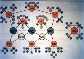
Once the lines of communication between the people, the program and the required physical space are established, a diagram is drawn that describes the relationships between the people, the spaces and the functions Because all of the interactive relationships could not be shown due to the crossing of lines causing confusion, a 3-dimensional model was developed and is shown below.
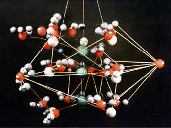
This model demonstrates the interaction between the program, the staff and the physical spaces required to be used. Many spaces and people are used either simultaneously, therefore several lines may interconnect. By taking close-up photos, each connection can be shown in greater detail, allowing interactive discussions about design of each department.
C
D
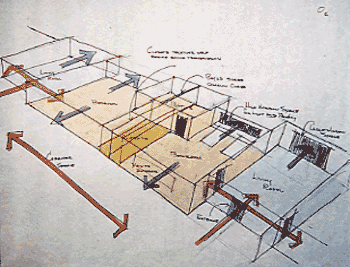
Many sketches are done to demonstrate the different "connection points" and lines of travel which had to be demonstrated both for staff and client. These sketches start the process of development of actual physical spaces that satisfies the connection requirements that were defined in previous steps.
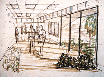
Additional sketches are eventually developed to more clearly demonstrate the "environmental" aspects of the schematics above. As more sketches are drawn, a better definition of the physical space is provided. The environment is intended to satisfy requirements of the design development program that continuously gets revised.
E
F
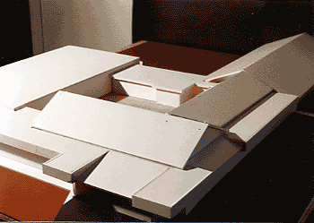
This is one of a series of basic "form" models designed to assist with the integration of the new buildings with existing structures. Photos were take from many different angles for discussions with the client. Many different models may be constructed based on a floor plan that reflects the conclusions drawn from the previous steps. The actual structure is shown below and is very similar to the model.
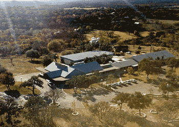
The final structure when added to the existing buildings.